内容
隐藏
In the vast world of electrical components, switches stand out as fundamental gatekeepers of power and signal flow. From the simplest home appliance to complex industrial machinery, switches are the critical interface between user command and system action. Among the diverse array of switch types, the Single Pole Single Throw (SPST) switch holds a position of ubiquitous importance due to its straightforward design and essential function. While seemingly basic, understanding the nuances of the SPST switch is crucial for engineers, designers, and procurement professionals aiming to select the most reliable and cost-effective components for their projects. This guide serves as your definitive resource, delving into the definition, operation, types, applications, and selection criteria for SPST switches, specifically tailored for demanding industrial and commercial environments. Our goal is to equip you with the knowledge needed to confidently choose the right SPST switch that meets your technical specifications and ensures optimal performance.
What Exactly is a Single Pole Single Throw (SPST) Switch?
Understanding the SPST switch begins with breaking down its name. It represents the most fundamental configuration of a switch, designed for a simple, yet critical, task: turning a single circuit on or off.
Decoding the Terminology: Pole and Throw Explained
To fully grasp the SPST concept, let’s clarify the terms ‘pole’ and ‘throw’:
- Pole: This refers to the number of separate electrical circuits the switch can control simultaneously. A ‘single pole’ switch, therefore, controls just one circuit.
- Throw: This indicates the number of output connection points each pole can connect to. A ‘single throw’ switch provides only one path for the circuit to be completed through the switch.
Combining these, a Single Pole Single Throw (SPST) switch is designed to control a single circuit by providing a single path for current flow. It has one input terminal and one output terminal. Its function is purely binary: it’s either connected or disconnected.

The Basic Function: Simple On/Off Control
The core purpose of an SPST switch is elegantly simple: it acts as a gate in an electrical circuit. When the switch is activated to the ‘on’ state, it closes the circuit, allowing electrical current to flow through from the input terminal to the output terminal, powering a device or enabling a function. When switched to the ‘off’ state, it opens the circuit, creating a break that stops the current flow. Think of it like a drawbridge controlling a single road – the bridge is either down (closed circuit, traffic flows) or up (open circuit, traffic stops). This fundamental On/Off switch capability makes it indispensable in countless applications.
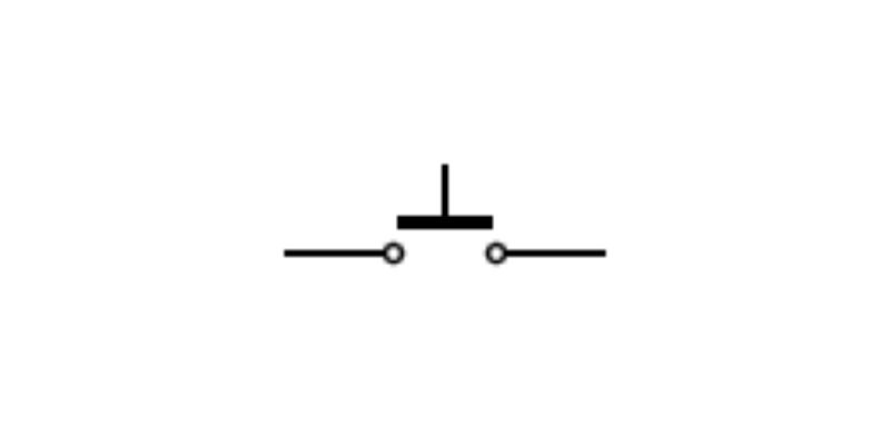
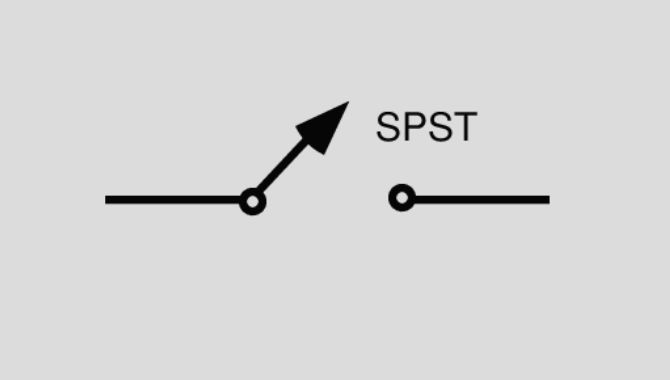
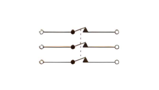
Visualizing the SPST Switch: Common Symbols
In electrical diagrams and schematics, switches are represented by standardized symbols. The schematic symbol (or circuit symbol) for an SPST switch clearly depicts its function. It typically shows two terminals and a movable contact (the ‘pole’) that can either bridge the gap between the terminals (Closed Circuit – On) or create a break (Open Circuit – Off).
[Image suggestion: Clear diagram illustrating the standard SPST circuit symbols in both the Normally Open (off by default) and Normally Closed (on by default) configurations, showing the open and closed states for each.]
How Does an SPST Switch Work? The Inner Mechanics
While the external function of an SPST switch is simple on/off control, its internal operation relies on a few key components working together seamlessly.
Key Components
At its heart, an SPST switch consists of three primary elements:
- Actuator: This is the part of the switch that the user or a mechanical system interacts with to change the switch’s state. Actuators come in many forms, including pushbuttons, toggles, rockers, sliders, rotary knobs, or even key-operated mechanisms. The choice of actuator often depends on the user interface requirements and the specific application.
- Contacts: These are the internal conductive pieces that physically make or break the electrical circuit. When the switch is ‘on’, the contacts touch, creating a low-resistance path for current. When ‘off’, they separate, creating an air gap that prevents current flow.
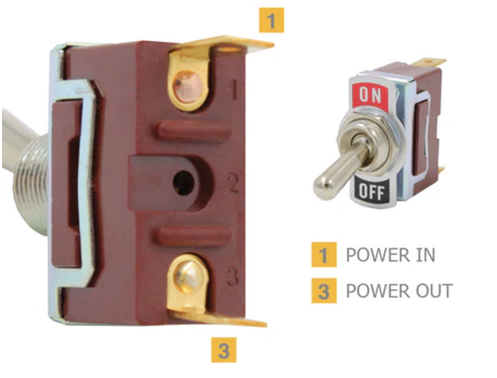
- Terminals: These are the external points where wires are connected to integrate the switch into the larger electrical circuit. An SPST switch has two terminals: one for the input and one for the output.
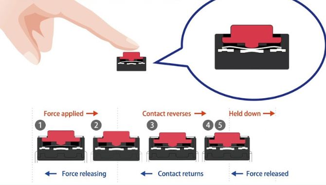
The Switching Mechanism
The actuator is mechanically linked to the movable contact(s). When the actuator is operated (e.g., a button is pressed, a toggle is flipped), it forces the movable contact to either connect with the fixed contact (closing the circuit) or separate from it (opening the circuit). The design of this mechanism determines whether the switch is momentary or latching, and dictates the physical force required for actuation. Different actuation mechanisms offer varying tactile feedback and are suited for different operational needs and environments.
Exploring the Main Types of SPST Switches
While all SPST switches perform the same basic on/off function, they come in variations based on their default state and how they respond to actuation. Understanding these types is crucial for selecting the correct switch for a specific circuit behavior.
Normally Open (NO) vs. Normally Closed (NC)
This classification refers to the state of the switch contacts when the actuator is in its resting or default position (not being operated).
- Normally Open (NO) Switches: In their default state, NO switches maintain an open circuit – the contacts are separated, and no current flows. When the actuator is operated (e.g., a button is pressed), the contacts close, completing the circuit and allowing current flow. They are often referred to as “push-to-make” switches. NO switches are commonly used for applications where an action should start only when the switch is actively engaged, such as activating a signal, starting a momentary process, or triggering an input.
- Normally Closed (NC) Switches: Conversely, NC switches maintain a closed circuit in their default state – the contacts are touching, allowing current to flow continuously. When the actuator is operated, the contacts separate, opening the circuit and interrupting the current flow. These are known as “push-to-break” switches. NC switches are frequently employed in safety circuits (like emergency stop buttons, where pressing the button breaks the circuit to halt machinery), alarm systems (where opening the circuit triggers an alarm), or applications where a function needs to be interrupted.

Momentary vs. Latching (Maintained) Actuation
This distinction relates to whether the switch stays in its actuated state after the user releases the actuator.
- Momentary Switches: These switches are only active while the actuator is being physically pressed, held, or operated. Once the force on the actuator is removed, the switch automatically returns to its default state (either NO or NC). Momentary switches are ideal for applications requiring temporary activation or user-controlled pulses, such as doorbell buttons, keyboard keys, reset buttons, or motor jogging controls.
- Latching (Maintained) Switches: These switches maintain their state after the actuator has been operated and released. If you switch it ‘on’, it stays ‘on’ until you actively switch it ‘off’ again, and vice versa. Common light switches are a prime example of latching switches. They are suitable for applications where a circuit needs to remain continuously on or off for extended periods without constant user interaction, such as power buttons for equipment, mode selectors, or main lighting controls.
Where are SPST Switches Used? Key Applications
The simplicity and cost-effectiveness of SPST switches make them ubiquitous across a vast range of commercial and industrial applications. Their primary role is straightforward on/off control.
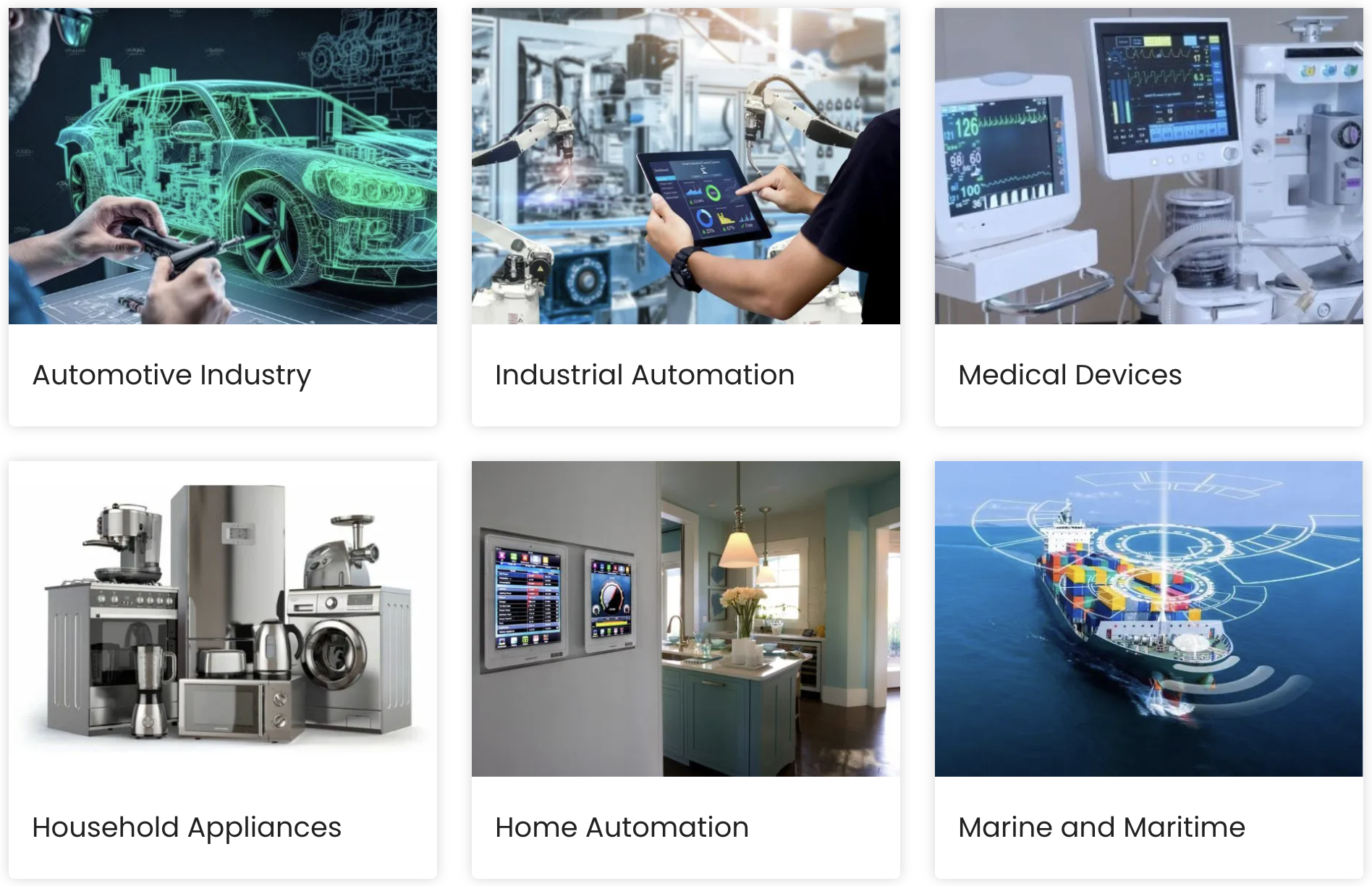
Industrial Control Panels & Machinery
SPST switches are workhorses in industrial settings. They are commonly used as main power switches, start/stop buttons for motors and processes, safety interlocks (often NC type), and simple function activation controls on machinery.
Automotive Systems
In vehicles, SPST switches control various functions like basic interior lighting, accessory power activation (e.g., for auxiliary lights or equipment), and sometimes simpler dashboard controls. Their reliability is key in these environments.
Commercial Appliances & Equipment
From coffee makers and power tools to office equipment and professional audio gear, SPST switches serve as the primary power on/off switch or activate specific, non-variable functions.
Building Systems & Lighting Control
The most familiar application is the standard wall light switch. SPST switches are also integral components in security systems, alarm panels, HVAC controls, and other building automation functions requiring simple on/off capability.
Test & Measurement Equipment
Benchtop power supplies, multimeters, signal generators, and other test gear often utilize SPST switches for power control, range selection, or input/output activation due to their reliability and clear state indication.
Advantages of Using SPST Switches
Despite the availability of more complex switches, the SPST switch remains a popular choice for many valid reasons, particularly in commercial and industrial design:
Simplicity and Ease of Use
Their operation is intuitive – typically just two states (on or off). This reduces user error and simplifies circuit design and troubleshooting.
Cost-Effectiveness
Generally, SPST switches have a simpler construction with fewer internal components compared to multi-pole or multi-throw switches. This often translates to a lower point, making them an economical choice for basic control needs.
Reliability
With fewer moving parts and contact points, well-designed SPST switches can offer high reliability and a long operational lifespan, especially crucial in industrial applications where downtime is costly.
Space Efficiency
SPST switches are available in a wide variety of sizes, including very compact footprints, making them suitable for applications where space on a panel or PCB is limited.
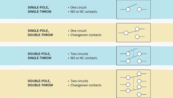
SPST vs. Other Common Switch Types (SPDT, DPDT)
While the SPST switch handles basic on/off tasks, it’s helpful to understand how it differs from other common configurations like SPDT and DPDT, especially when selecting components.
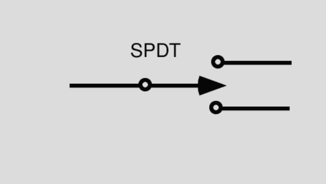
SPST vs. SPDT (Single Pole Double Throw)
A Single Pole Double Throw (SPDT) switch also controls a single circuit (Single Pole), but it offers two possible output paths (Double Throw). Instead of just opening or closing one path like an SPST, an SPDT switch directs the input current flow to one of two output terminals. Think of it as a fork in the road, where the switch determines which path the traffic takes. It typically has three terminals: one common input and two outputs.
- Key Difference: SPST provides simple on/off control for one circuit. SPDT switches a single input between two different output paths or circuits (often called a changeover switch).
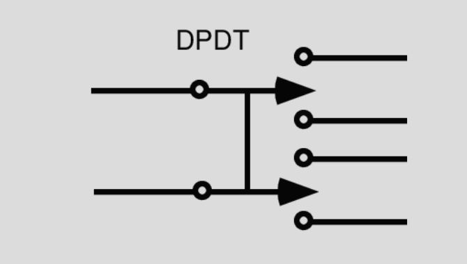
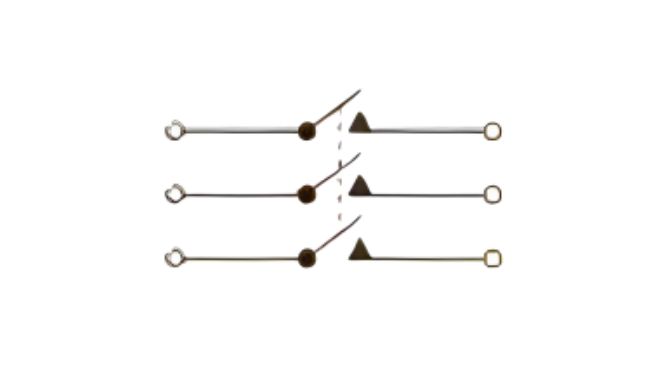
SPST vs. DPDT (Double Pole Double Throw)
A Double Pole Double Throw (DPDT) switch is essentially two SPDT switches mechanically linked and operated by a single actuator. It has two independent input terminals (Double Pole), and each input can be connected to one of two output terminals (Double Throw). This allows a DPDT switch to control two completely separate circuits simultaneously, switching each between two options. It typically has six terminals.
- Key Difference: SPST controls one circuit with a simple on/off function. DPDT controls two separate circuits simultaneously, each with a changeover function similar to an SPDT.
Understanding these differences ensures you select the switch with the appropriate complexity for your circuit design, avoiding unnecessary cost or connections when a simple SPST will suffice.
How to Choose the Right SPST Switch for Your Application (Buyer’s Guide)
Selecting the ideal SPST switch goes beyond just needing an on/off function. For industrial and commercial applications, several factors must be carefully considered to ensure performance, reliability, and safety. This section addresses the critical commercial investigation intent and aims to fill the content gaps often found in basic explanations.
Defining Your Electrical Requirements
This is the most fundamental step. Mismatching electrical ratings can lead to switch failure or hazardous conditions.
- Voltage Rating: Specify the maximum voltage (AC or DC) the switch will encounter in the circuit. The switch’s rating must exceed this operating voltage with a suitable safety margin.
- Current Rating: Determine the maximum continuous current the switch needs to carry when closed. The switch’s current rating (often specified for resistive loads) must be higher than the maximum operating current. Consider inrush currents for inductive or capacitive loads, which might require a higher rating.
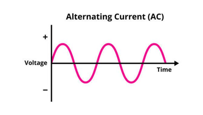
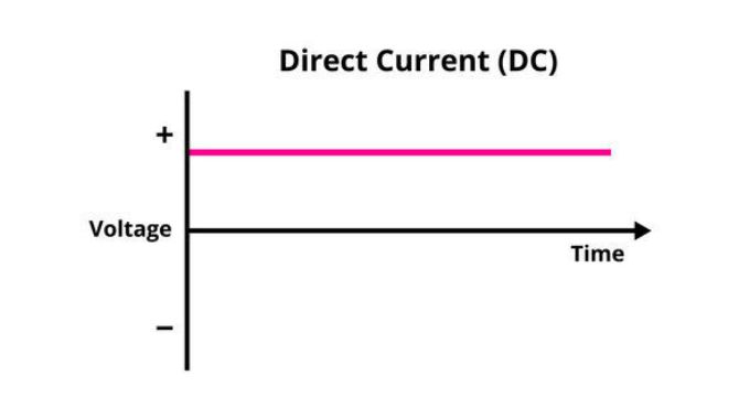
- AC vs. DC: Ratings often differ for AC and DC operation due to how arcs are extinguished when the contacts open. Ensure the switch is rated appropriately for the type of current in your application.
Considering the Operating Environment
The environment where the switch operates significantly impacts its longevity and performance.
- Temperature Range: Ensure the switch’s operating temperature range aligns with the minimum and maximum temperatures expected in the application environment.
- Ingress Protection (IP Rating): This is crucial for industrial control and harsh environments. The IP rating (e.g., IP65, IP67) indicates the switch’s degree of protection against dust and moisture ingress. Choose a rating appropriate for the level of exposure.
- Vibration and Shock Resistance: For applications in machinery or mobile equipment, verify the switch’s ability to withstand mechanical vibration and shock without malfunctioning or failing prematurely.
Actuation Type and Mounting Style
These relate to the user interface and physical integration.
- Actuation Type: Choose based on user interaction needs: Toggle (lever), Rocker (pivoting surface), Pushbutton (momentary or latching press), Slide (linear motion), Rotary (knob turning), Keylock (security). Consider ergonomics and required actuation force.
- Mounting Style: How will the switch be installed? Common options include Panel mount (through a hole in an enclosure), PCB mount (soldered directly onto a printed circuit board – through-hole or surface mount).
Mechanical and Electrical Lifespan
Manufacturers typically specify the expected lifespan in terms of operating cycles.
- Mechanical Life: The number of cycles the switch mechanism can endure before physical failure.
- Electrical Life: The number of cycles the switch can perform under a specified electrical load before contact degradation affects performance. Choose a switch with a lifespan rating suitable for the expected usage frequency in your application.
Material and Construction
The materials used impact durability, conductivity, and environmental resistance.
- Contact Materials: Common materials include silver alloys (good conductivity, cost-effective), gold plating (excellent for low-current signals, corrosion resistance), or other alloys depending on the load requirements.
- Housing Materials: Typically durable plastics (like nylon or PBT) or metal, chosen for strength, temperature resistance, and flammability ratings (e.g., UL 94V-0).
Certifications and Standards
Compliance with relevant standards is often mandatory, especially for products sold in specific markets.
- Look for certifications like UL (Underwriters Laboratories), CSA (Canadian Standards Association), CE (Conformité Européenne), RoHS (Restriction of Hazardous Substances), and others relevant to your industry and region. This ensures safety and regulatory compliance.
NO or NC, Momentary or Latching?
Revisit the functional requirements of your circuit. Does the circuit need to be on or off by default? Does the action need to be temporary or sustained? Answering these questions determines whether you need an NO or NC configuration, and momentary or latching actuation.
By systematically evaluating these factors against your application’s specific needs, you can confidently select an SPST switch that provides reliable, safe, and long-lasting performance.
Finding a Reliable SPST Switch Supplier
Once you’ve defined the specifications for your ideal SPST switch, the next step is sourcing it from a dependable or supplier. The quality of the component and the support from the supplier are critical for project success.
What to Look For in a Manufacturer/Supplier
- Product Range and Customization: Does the supplier offer a wide variety of SPST switches covering different ratings, actuation types, and mounting styles? Can they provide customization options if standard products don’t perfectly fit?
- Quality Control and Certifications: Does the supplier adhere to stringent quality control processes (e.g., ISO 9001)? Are their products reliably certified to relevant standards (UL, CE, RoHS)?
- Technical Support and Documentation: Is comprehensive technical information readily available, including detailed datasheets with all necessary specifications? Does the supplier offer responsive technical support to answer questions?
- Lead Times and Supply Chain Reliability: Can the supplier meet your required delivery timelines? Do they maintain stable stock levels or have a reliable production schedule?
- Reputation and Experience: Does the supplier have a proven track record in the industry and experience serving customers with similar needs?
Why Partner With WEUP?
At WEUP, we understand the critical role that even the simplest components like SPST switches play in your designs. We pride ourselves on offering a comprehensive range of high-quality, reliable switches designed for demanding industrial and commercial applications. Our commitment includes [mention 2-3 key strengths, e.g., rigorous quality testing, extensive customization capabilities, expert technical support, adherence to international standards]. We work closely with engineers and procurement teams to ensure you get the perfect switching solution.
Need help selecting the perfect SPST switch? Our experts are ready to assist. Contact us today for a consultation or request a quote.
Conclusion: The Simple Power of the SPST Switch
The Single Pole Single Throw (SPST) switch, in its elegant simplicity, remains a cornerstone of electrical control. Its straightforward on/off function, combined with its inherent cost-effectiveness and potential for high reliability, makes it an indispensable component across countless industrial and commercial sectors. From activating machinery to controlling lighting, the SPST switch provides a fundamental, dependable interface.
Choosing the right SPST switch, however, requires careful consideration of electrical ratings, environmental conditions, actuation needs, and required certifications. By understanding the different types (NO, NC, momentary, latching) and systematically evaluating the selection criteria outlined in this guide, you can ensure you source a component that perfectly matches your application’s demands.
Explore our wide range of high-quality SPST switches or get in touch with our team at [Your Company Name] to discuss your specific requirements. Let us help you find the reliable switching solution you need.
Application areas of different voltages
The voltage of the switch is divided into DC switch and AC switch. Different voltages have different application fields. Below I will specifically introduce the application of different voltages.
| Voltage | Application |
| 12V | Automotive Electrical Systems UPS (Uninterruptible Power Supply) Solar Power Systems LED Lighting Portable Electronics |
| 24V | Automotive and Truck Applications Power Tools and Equipment Small Electric Vehicles Industrial Automation Equipment |
| 36V | Electric Bicycles and Scooters Power Tools Small Electric Vehicles |
| 48V | Electric Bicycles and Scooters Electric Vehicles (Light) Energy Storage Systems Power Tools |
| 110V-120V | Residential Power Systems Electronics Power Tools |
| 220V-240V | Commercial Power Supply Industrial Equipment Large Appliances |
Summary of Applications:
| Configuration | Applications |
|---|---|
| ON OFF | Ligh |
| ON ON | Circuit selecti |
| ON OFF ON | Fan spee |
| (ON) OFF ON | Vehicle |
| (ON) OFF (ON) | Motor direc |
Features
After selecting the voltage, you can choose the specific switch type for your application.
| Switch Type | Features |
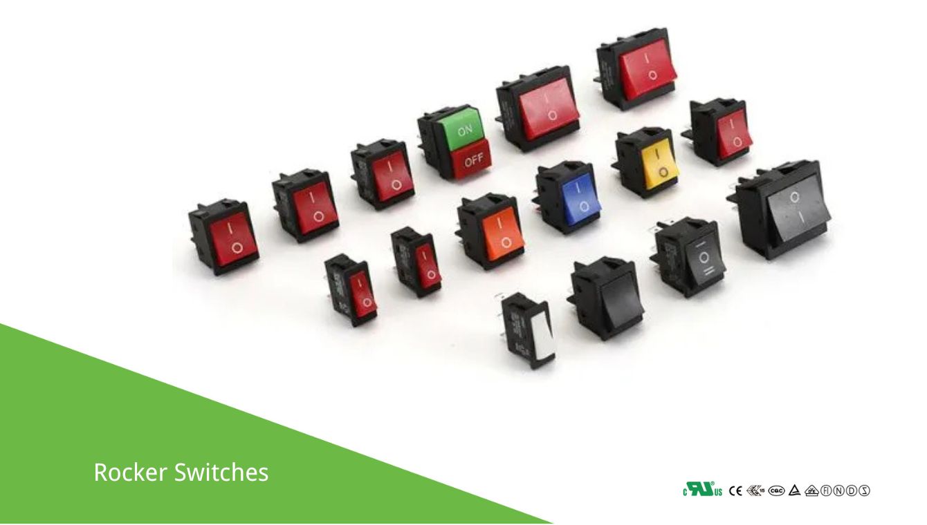
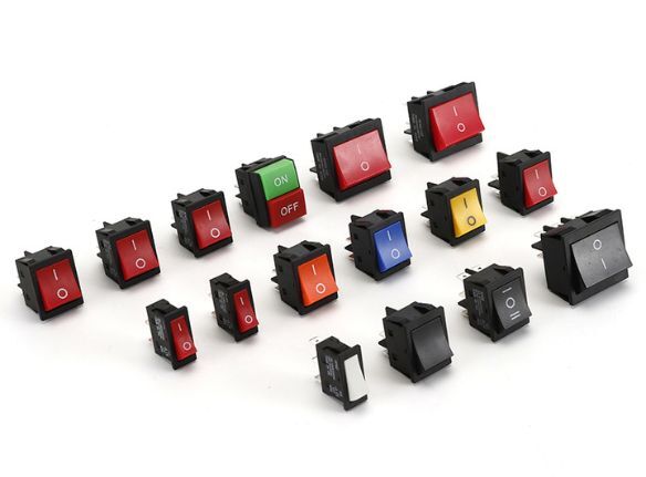 Rocker Switch Rocker Switch |
A rocker switch features a pivoting mechanism for on/off control, is durable, easy to operate, and comes in various configurations, sizes, and designs, suitable for both residential and industrial applications. |
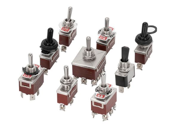
 Toggle Switch Toggle Switch |
A toggle switch has a lever that moves up and down to control electrical circuits. It offers a reliable on/off mechanism, comes in various sizes, and is commonly used in industrial and household devices. |
 Electromagnetic Switches Electromagnetic Switches |
Electromagnetic switches use an electromagnet to control the opening and closing of circuits. They offer precise, remote operation, are commonly used in relays, solenoids, and automated systems for efficient switching. |
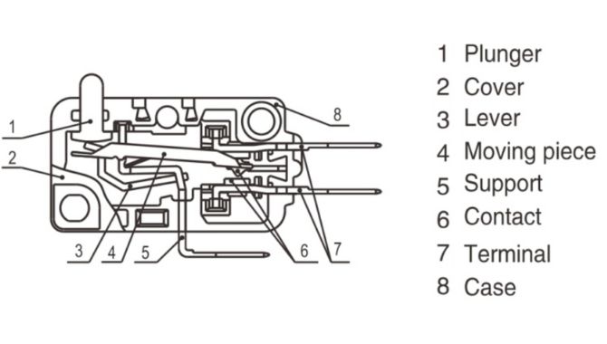
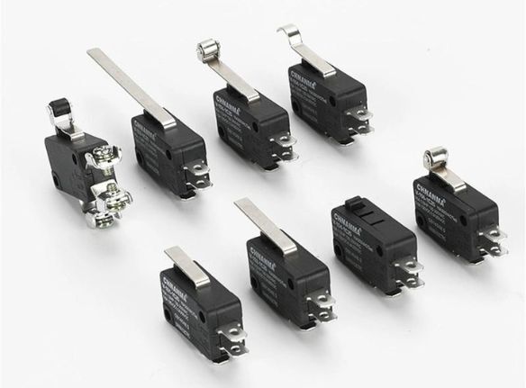 Micro Switch Micro Switch |
A micro switch is a small, highly sensitive switch activated by minimal physical force. It provides precise, reliable operation in response to motion, commonly used in safety devices, appliances, and machinery controls. |
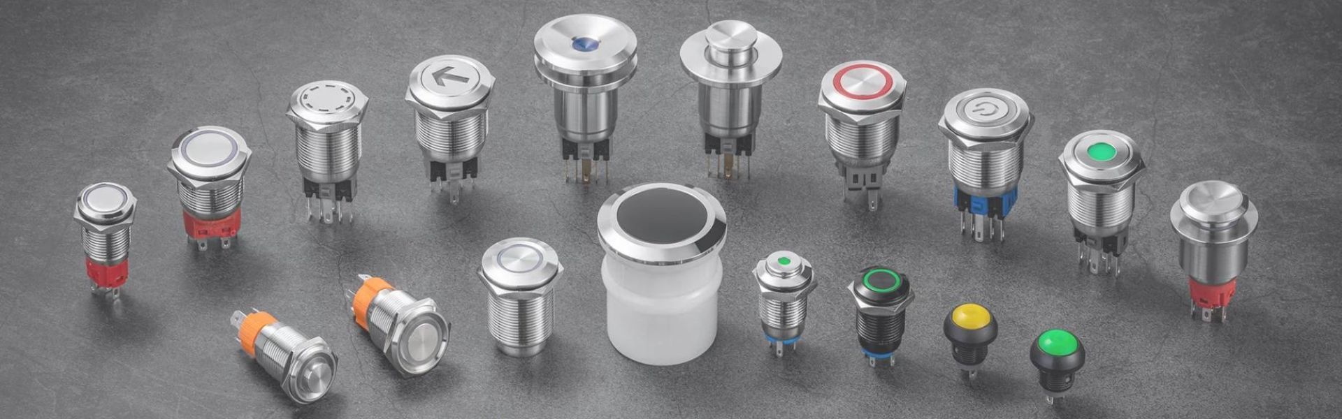
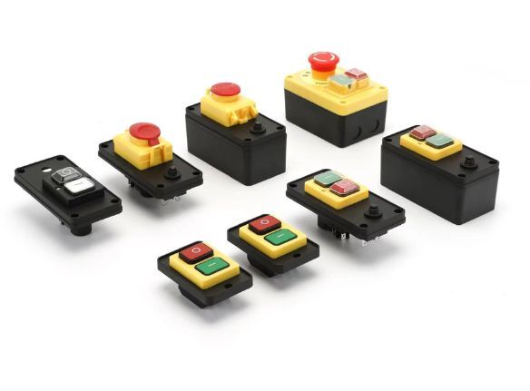
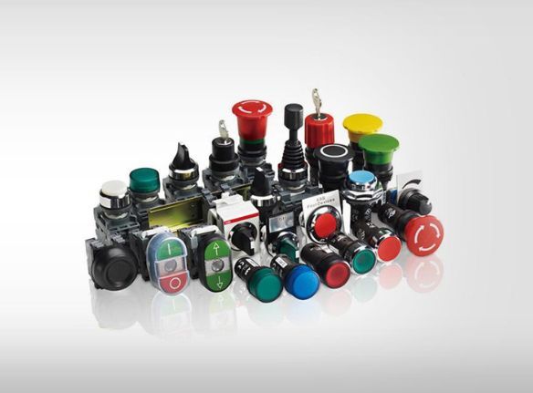 Push Button Switch Push Button Switch |
A push button switch is a simple on/off mechanism activated by pressing a button. It is compact, easy to operate, and widely used in electronics, appliances, and control panels for various applications. |
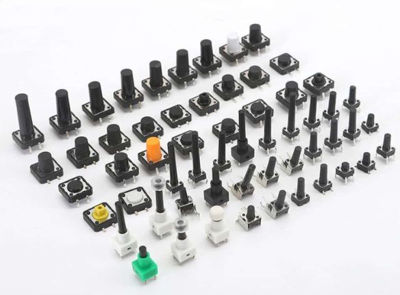 Tactile Switches Tactile Switches |
Tactile switches provide feedback through a slight “click” when pressed, offering a reliable and responsive action. Compact and durable, they are commonly used in electronic devices, keypads, and control panels. |
Related Resources
Single Pole Double Throw (SPDT) Switch