
Switch configuration · SPST
Single Pole Single Throw Switch (SPST)
An SPST switch opens or closes one electrical path with one actuator. Use this page to understand the basic ON/OFF function, compare real WEUP rocker examples, and prepare a practical sourcing request.
- 1 switching pole
- 1 ON/OFF path
- Simple circuit control
Circuit function
What is a SPST switch?
“Single pole” means the switch controls one electrical path. “Single throw” means that pole has one switched output. In the maintained ON-OFF form, the actuator either completes the path or opens it.
SPST is the simplest of the common pole-and-throw configurations, but the physical switch still has to match the actual load, panel cutout, terminal style and environment.
For a deeper circuit explanation, read the SPST switch guide.
Real product examples
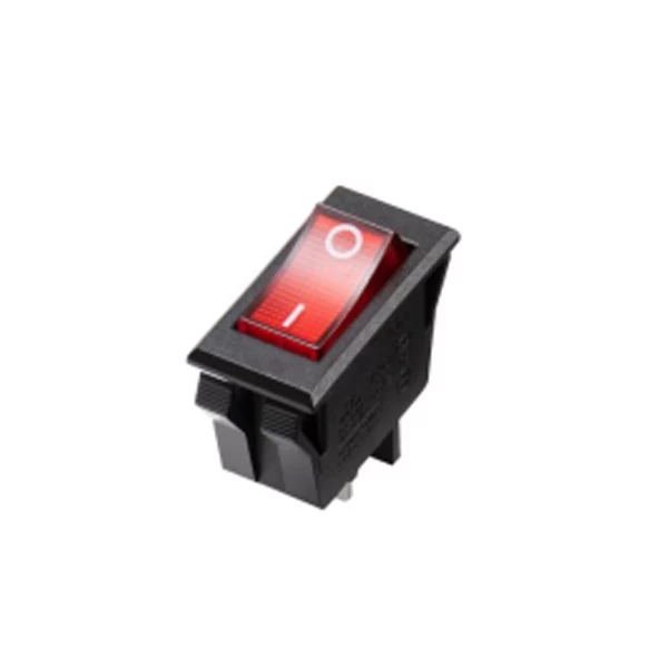
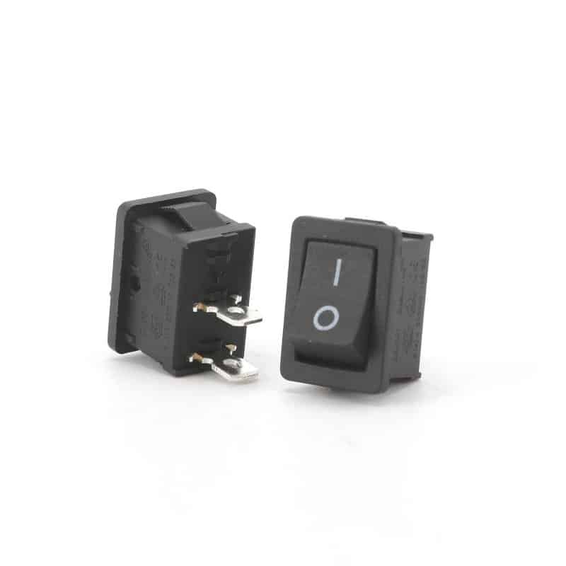
SPST switch product formats
These are real switch images from the WEUP WordPress media library. They show physical formats only; the exact model drawing remains the authority for ratings, terminals and action.
Configuration comparison
SPST vs. other switch configurations
Use pole and throw requirements to separate circuit functions before choosing a rocker, toggle or other actuator style.
| Configuration | Poles | Throws per pole | Control logic | Use when |
|---|---|---|---|---|
| SPST | 1 | 1 | One circuit ON/OFF | One path must be opened or closed |
| SPDT | 1 | 2 | One common selects between two paths | Changeover or source/load selection is needed |
| DPST | 2 | 1 | Two circuits ON/OFF together | Two isolated paths follow one actuator |
| DPDT | 2 | 2 | Two circuits change between two paths | Dual-circuit changeover or reversing logic is needed |
Related pages: SPDT switch page, DPST switch page, pole-and-throw configuration guide.
Buyer checklist
How to specify the right SPST switch
A useful RFQ starts with the circuit and installation. These checks help prevent a visual match from becoming an electrical or mechanical mismatch.
Switching action
Confirm maintained ON-OFF or a momentary action. The state must match the equipment logic.
Electrical load
Provide voltage, current and load type. Do not select only from the switch’s appearance.
Terminal format
Specify quick-connect, solder or another required terminal form and orientation.
Mounting dimensions
Share the panel cutout, available depth and retention method.
Illumination
State whether an indicator is required and how it should behave in the circuit.
Operating environment
Describe temperature, dust, moisture, vibration and cleaning conditions.
Application fit
Where SPST switches are considered
Application fit depends on the complete circuit, load, mounting and operating environment—not the configuration name alone.
Equipment power control
Straightforward ON/OFF control for one documented electrical path.
Appliance interfaces
Panel-mounted switching where cutout, depth and terminal access are defined.
Lighting circuits
Simple control of one lighting path when the switch is suitable for the load.
Control panels
A clear two-state operator control for machinery and subsystem interfaces.
Accessory circuits
Single-path control for equipment accessories and auxiliary functions.
Custom operator panels
Color, marking and illumination can be discussed after the circuit is fixed.
Faster sourcing
What to send with your inquiry
A drawing or current sample is the fastest reference. Otherwise, send the project facts in this checklist.
- Required switching action
- Voltage, current and load type
- Terminal style or circuit drawing
- Panel cutout and installation depth
- Illumination and marking needs
- Operating environment
- Target quantity and schedule
- Photos or sample reference
FAQ
Single Pole Single Throw Switch questions
What does SPST mean on a switch?
SPST means single pole, single throw. One electrical path is opened or closed by one actuator.
Is an SPST switch always ON-OFF?
A maintained SPST switch commonly provides ON-OFF control, while a momentary SPST design returns when released. Confirm the required action.
Does every SPST switch have two terminals?
A basic non-illuminated SPST circuit often uses two switching terminals, but illuminated versions can include additional lamp terminals.
Can an SPST switch control a motor?
Only when the selected switch, load behavior and circuit design are suitable. Provide the motor and inrush details for review.
What information is needed for a quote?
Send the action, electrical load, terminals, panel cutout, environment, quantity and any drawing or sample reference.
Need a SPST switch matched to your project?
Share the circuit, load, terminal and panel requirements. The WEUP team can use those details to discuss a suitable product route.