
Switch configuration · DPST
Double Pole Single Throw Switch (DPST)
A DPST switch opens or closes two independent circuits with one actuator. Use this page to compare real WEUP rocker configurations, understand the circuit function, and prepare a clear sourcing request.
- 2 independent poles
- 1 ON/OFF path per pole
- 1 shared actuator
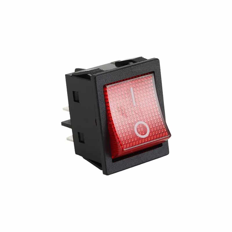
Two circuits switched at the same time
Rocker or toggle, depending on the application
Load, action, terminals, cutout and environment
Circuit function
What is a DPST switch?
“Double pole” means the device has two separate switching poles. “Single throw” means each pole connects to one output path. Mechanically, both poles move together, so one action turns both circuits on or off.
This arrangement is useful when a design needs simultaneous control without combining the two electrical paths. It can also be used when both conductors or two related loads must be switched together, provided the selected device is suitable for the actual circuit.
For a deeper circuit explanation, see the DPST switch buyer guide.
Real product examples
DPST rocker switch configurations
The images below show physical DPST rocker switch examples already in the WEUP media library. They are visual references for shape and terminal arrangement—not universal specification drawings.
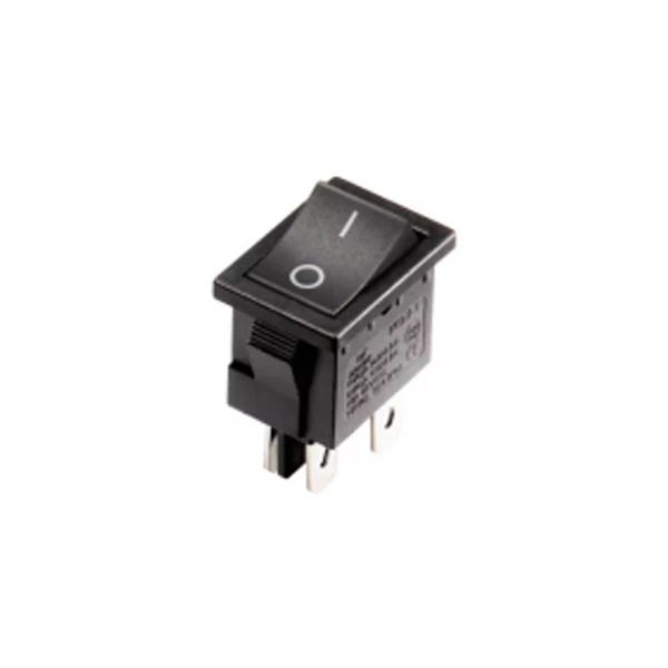
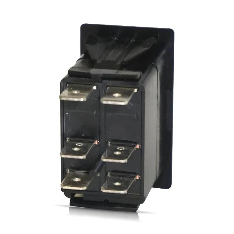
Configuration comparison
DPST vs. SPST, SPDT and DPDT
Start with the circuit function before choosing the actuator style. The table separates pole and throw requirements so similarly named switches do not end up on the same purchasing list.
| Configuration | Poles | Throws per pole | Typical control logic | Use when |
|---|---|---|---|---|
| SPST | 1 | 1 | One circuit ON/OFF | Only one electrical path must be opened or closed |
| SPDT | 1 | 2 | One common switches between two paths | A circuit needs changeover or selection |
| DPST | 2 | 1 | Two circuits ON/OFF together | Two isolated paths must follow one actuator |
| DPDT | 2 | 2 | Two circuits change between two paths | Dual-circuit changeover or reversing logic is required |
Need more detail? Compare the full SPST, SPDT, DPST and DPDT configuration guide, or review the related DPDT switch page.
Buyer checklist
How to specify the right DPST switch
A useful RFQ describes the circuit and installation before asking for a price. These six checks prevent a visual match from becoming an electrical mismatch.
Switching action
Confirm maintained ON-OFF or a momentary action. The actuator state must match the control logic.
Electrical load
Provide voltage, current and load type. Motor, resistive and electronic loads can require different selection.
Terminal layout
Share the required terminal style and wiring drawing. Do not infer function from terminal count alone.
Mounting dimensions
State panel cutout, available depth and retention method so the housing fits the equipment.
Illumination
Specify whether a lamp is needed, its circuit behavior and the intended supply. Extra terminals may be present.
Operating environment
Describe temperature, dust, moisture, vibration and panel conditions so suitable options can be reviewed.
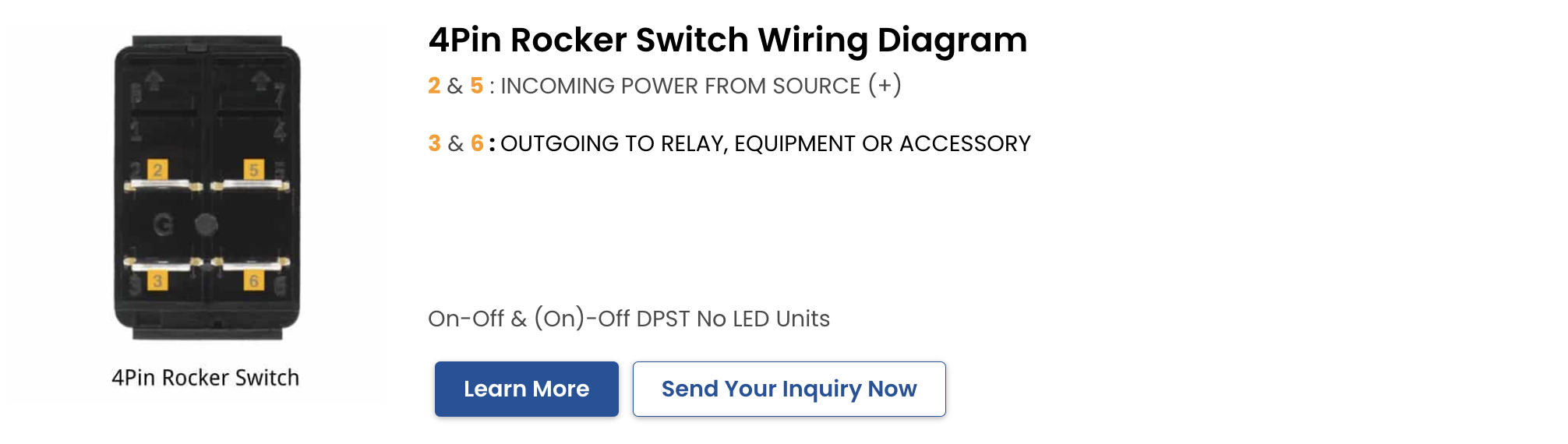
For broader installation context, see the toggle switch wiring guide. Always isolate power and follow the equipment manufacturer’s instructions.
Application fit
Where DPST switches are considered
DPST switching is useful wherever two isolated paths need coordinated ON/OFF control. Suitability still depends on the exact product rating and the system design.
Equipment power control
Coordinated control of two conductors or related circuits in machinery and appliance designs.
Control panels
A single visible actuator can operate two independent control paths while keeping them electrically separate.
Lighting and accessory circuits
Two related loads can be switched together when the selected device and circuit design are suitable.
HVAC and appliance assemblies
Panel-mounted switching where mechanical fit, load behavior and terminal access are all defined.
Industrial subsystems
Simultaneous switching within a documented control scheme, reviewed against the equipment requirements.
Custom operator interfaces
Rocker style, color, marking and illumination can be discussed after the electrical configuration is fixed.
Faster sourcing
What to send with your inquiry
A drawing or current sample is the fastest way to compare the right series. If neither is available, send the project facts in this checklist.
- Required DPST action
- Voltage, current and load type
- Terminal style or wiring drawing
- Panel cutout and installation depth
- Illumination and marking needs
- Operating environment
- Target quantity and schedule
- Photos or sample reference
FAQ
Double pole single throw switch questions
What does DPST mean on a switch?
DPST means double pole, single throw. It describes two separate switching poles that each open or close one path, with both poles operated by the same actuator.
Is a DPST switch the same as a DPDT switch?
No. A DPST switch provides ON/OFF control for two circuits. A DPDT switch provides two selectable output paths for each of two poles, so it supports changeover logic.
Does every DPST rocker switch have four terminals?
No. A basic non-illuminated DPST circuit often uses four switching terminals, but illuminated designs can include additional lamp terminals. Use the model drawing to identify each connection.
Can one DPST switch control two devices?
It can switch two separate circuits together when the electrical load, wiring design and selected switch ratings are suitable. The final circuit should be reviewed by a qualified professional.
What information is needed for a DPST switch quote?
Send the action, voltage, current, load type, terminal style, mounting dimensions, illumination requirement, environment, quantity and any available drawing or product sample.
Need a DPST switch matched to your project?
Share your circuit requirement, load details, panel dimensions and photos. The WEUP team can use that information to discuss a suitable product route and customization needs.