
10-Pin Rocker Switch Wiring Diagram
A comprehensive guide to correctly wiring your 10-pin rocker switch, featuring detailed diagrams and step-by-step instructions from WEUP, your reliable partner in premium switch manufacturing.
Understanding the 10-Pin Rocker Switch
A 10-pin rocker switch is a versatile component commonly used in automotive, marine, industrial control panels, and household appliances for controlling multiple circuits or functions. The 10 pins allow for complex switching configurations such as On-Off-On, (On)-Off-(On), or controlling independent circuits with a single actuator.
Proper wiring is crucial for safety and functionality. This guide provides clear diagrams and descriptions to help engineers, technicians, and DIY enthusiasts achieve reliable connections.
Standard 10-Pin Layout & Pin Identification
Pin Configuration (Bottom View):
- 1 Common Terminal 1 (C1)
- 2 Normally Open 1 (NO1)
- 3 Normally Closed 1 (NC1)
- 4 Common Terminal 2 (C2)
- 5 Normally Open 2 (NO2)
Pin Configuration (Continued):
- 6 Normally Closed 2 (NC2)
- 7 Illumination Anode (+)
- 8 Illumination Cathode (-)
- 9 Auxiliary Terminal (if applicable)
- 10 Ground/Frame
Note: Always refer to the specific datasheet for your WEUP switch model as pin assignments can vary slightly between designs (e.g., DPST, DPDT configurations).
Key Features of WEUP 10-Pin Rocker Switches
- High-current capacity (up to 20A @ 12V DC)
- IP67 waterproof rating (selected models)
- Built-in LED illumination (multiple colors)
- Vibration and shock resistant
- UL, CE, RoHS certified
Safety First
- Always disconnect power before wiring.
- Use appropriate wire gauge for the current.
- Secure connections with proper terminals.
- Consult a qualified electrician if unsure.
Detailed Wiring Diagrams
Diagram 1: Basic DPDT (Double Pole Double Throw) Configuration
This is the most common configuration for a 10-pin rocker switch, allowing control of two separate circuits with On-Off-On functionality.
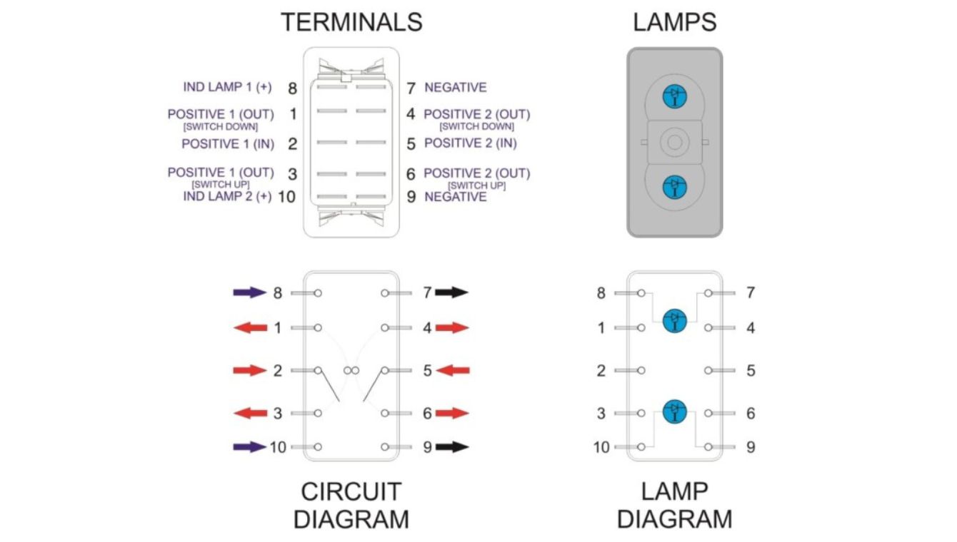
Wiring Instructions:
- Power Input: Connect your positive power source (e.g., +12V) to both Common terminals C1 (Pin 1) and C2 (Pin 4).
- Load Connection – Position 1: When the switch is toggled to the first ON position, C1 connects to NO1 (Pin 2) and C2 connects to NO2 (Pin 5). Connect your Load 1 to NO1 and Load 2 to NO2.
- Load Connection – Position 2: When toggled to the opposite ON position, C1 connects to NC1 (Pin 3) and C2 connects to NC2 (Pin 6). Connect alternate Loads 3 and 4 to these pins if needed.
- Illumination: Connect Pin 7 (Anode +) to a switched or constant positive source (often via a resistor). Connect Pin 8 (Cathode -) to ground. The LED will illuminate when power is applied.
- Ground: Connect Pin 10 (Frame Ground) to the chassis or common ground point for safety and EMI reduction.
💡 Application: Perfect for controlling two motors (forward/reverse) or selecting between two power sources (e.g., Battery 1 / Battery 2).
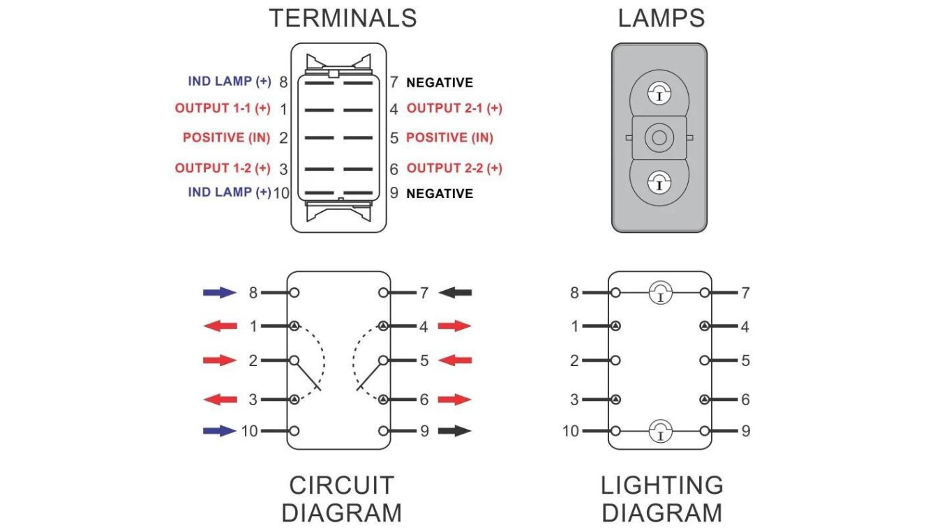
Diagram 2: Independent On-Off Control for Two Circuits
This setup uses the switch as two completely independent SPST switches in one housing, controlling two circuits with a simple On/Off action.
Wiring Instructions:
- Circuit 1: Connect power source to C1 (Pin 1). Connect your first device (e.g., light) to NO1 (Pin 2). Leave NC1 (Pin 3) unused or insulated.
- Circuit 2: Connect the same or a different power source to C2 (Pin 4). Connect your second device (e.g., fan) to NO2 (Pin 5). Leave NC2 (Pin 6) unused.
- Illumination Options:
- Independent Illumination: Wire LED pins (7 & 8) to an independent circuit so the light is always on when the vehicle/device has power.
- Switched Illumination: Wire the LED anode (Pin 7) to the output of one of the circuits (e.g., NO1) so it only lights when that circuit is active.
- Ensure all device negatives are connected to the system ground.
⚙️ WEUP Advantage: Our switches feature silver-plated contacts for minimal voltage drop across independent circuits, ensuring both devices receive full power.
Troubleshooting Common Wiring Issues
Quick reference guide to diagnose and solve common problems with 10-pin rocker switch installations.
Switch gets hot
Indicates excessive current or poor connection.
- ✓ Check load amperage vs. switch rating (e.g., 20A max).
- ✓ Ensure wire gauge is sufficient (e.g., 12 AWG for 20A).
- ✓ Tighten all terminal screws.
LED doesn’t light
The illumination circuit is not complete.
- ✓ Verify polarity (Pin 7 = Anode +, Pin 8 = Cathode -).
- ✓ Check for a built-in resistor; add one if needed (e.g., 1kΩ for 12V).
- ✓ Test with a multimeter for voltage at pins 7 & 8.
Only one position works
Miswiring of the common or load terminals.
- ✓ Confirm power is connected to both C1 and C2 for DPDT.
- ✓ Verify loads are connected to correct NO/NC pins.
- ✓ Inspect for bent pins inside the switch housing.
Need a Custom Wiring Solution?
WEUP offers personalized customization services. If your project requires a non-standard pinout, higher current rating, or special illumination, our engineering team can develop a switch tailored to your exact specifications.
Your Reliable Partner for Premium Switches
WEUP has been a cornerstone of reliability in the Chinese switch manufacturing industry for over two decades, participating in the formulation of national switch industry standards.
Decades of expertise in designing and manufacturing reliable switches.
Our switches’ stable performance helps clients lower operational expenses.
Quality management certified, alongside UL, CE, and RoHS compliance.
Building 3, Huayi E-commerce Park, Chengnan Street, Yueqing, Zhejiang, China, 325608