
Multi-pole switch configuration · 3PDT
3PDT Switch
A 3PDT switch routes three independent common circuits between two output paths with one actuator. Use this page to compare a real WEUP rocker format with the three-pole changeover diagram.
- 3 independent common poles
- 2 outputs per pole
- 1 shared actuator
Circuit function
What is a 3PDT switch?
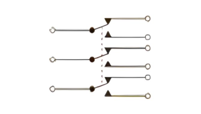
“Three pole” means three independent common circuits are controlled. “Double throw” means each common can connect to one of two outputs. All three poles change position together.
Common actions include maintained ON-ON and center-OFF variants, but the action must be specified rather than assumed. The same 3PDT logic can appear in rocker, toggle or other mechanical formats.
A basic contact set is often discussed as three groups of one common and two outputs. Illumination or auxiliary functions can change the visible terminal count.
Product and circuit references
3PDT visual references
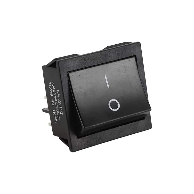
The product photo and contact diagram are first-party WEUP media. The diagram explains the logic; the selected model drawing remains the authority for terminal numbering and ratings.
Multi-pole comparison
3PDT vs. other multi-pole configurations
Separate pole count, throw count and switch action before choosing the housing or actuator style.
| Configuration | Poles | Throws per pole | Control logic | Use when |
|---|---|---|---|---|
| 3PST | 3 | 1 | Three circuits ON/OFF together | Three isolated paths must follow one actuator |
| 3PDT | 3 | 2 | Three circuits change between two paths | Three coordinated changeover channels are required |
| 4PST | 4 | 1 | Four circuits ON/OFF together | Four isolated paths must follow one actuator |
| 4PDT | 4 | 2 | Four circuits change between two paths | Four coordinated changeover channels are required |
Related pages: 3PST switch page, 4PDT switch page, toggle switch wiring guide.
Buyer checklist
How to specify the right 3PDT switch
Multi-pole requirements need a complete circuit map. These checks keep one visual match from becoming a wiring or installation mismatch.
Required switch positions
Specify ON-ON, ON-OFF-ON, momentary behavior or another documented action.
Three changeover channels
Provide all three common circuits and both output paths in one clear diagram.
Load on each pole
State voltage, current and load type for all three channels.
Terminal map
Define terminal style, physical orientation, spacing and numbering requirements.
Mounting envelope
Share cutout, panel thickness, depth, retention and operator-clearance needs.
System protection
Describe interlocking, transient protection and environmental conditions in the wider circuit.
Application fit
Where 3PDT switches are considered
Application fit depends on the complete circuit, load, mounting and operating environment—not the configuration name alone.
Three-channel mode selection
Three isolated common paths change between two documented operating states.
Signal routing
Coordinated three-path selection in suitable control or low-level circuits.
Equipment changeover
One actuator changes three independent channels together.
Audio and instrumentation routing
Multiple isolated conductors can be switched together when contact and signal requirements are compatible.
Custom control panels
Rocker format and markings can present two coordinated operating modes.
Protected reversing logic
Three-pole changeover may support specialized circuits when the full system design is appropriate.
Faster sourcing
What to send with your inquiry
A model drawing or current sample is the fastest reference. Otherwise, send the project facts below.
- Complete multi-pole circuit map
- Required switching action
- Voltage, current and load on every pole
- Terminal style and physical layout
- Panel dimensions and installation depth
- Operating environment
- Target quantity and schedule
- Existing drawing, photo or sample
FAQ
3PDT Switch questions
What does 3PDT mean on a switch?
3PDT means three pole, double throw. Three independent common circuits each change between two outputs under one actuator.
What is the difference between 3PST and 3PDT?
3PST opens or closes three circuits. 3PDT changes three circuits between two output paths.
Does a 3PDT switch always have nine terminals?
A basic non-illuminated 3PDT contact set is often arranged as three groups of three switching terminals, but auxiliary functions can add terminals.
Is every 3PDT switch ON-ON?
No. ON-ON, ON-OFF-ON and momentary actions are possible. The exact action must be part of the sourcing specification.
What information is needed for a 3PDT quote?
Send the action, three-channel circuit map, loads, terminals, mounting dimensions, environment, quantity and available drawings.
Need a 3PDT switch matched to your project?
Share the circuit, action, loads, terminal layout and panel requirements. WEUP can use those details to discuss a suitable sourcing route.