
What Is a Double Pole Double Throw (DPDT) Switch?
A comprehensive guide to understanding DPDT switches, their operation, applications, and why they're a versatile component in electrical and electronic circuits.
DPDT Switch Overview
Two Poles
Controls two completely separate circuits simultaneously with a single actuator.
Double Throw
Each pole connects to one of two output terminals, providing two distinct on states.
Versatile Switching
Can function as two independent SPDT switches or be wired for more complex tasks like reversing polarity.
Common Applications
Widely used in motor control, industrial controls, instrumentation, and complex switching panels.
Understanding the DPDT Switch
A Double Pole Double Throw (DPDT) switch is an electromechanical device that allows you to control the flow of electricity in two separate circuits, each with two possible paths. It's like having two independent SPDT (Single Pole Double Throw) switches operating in unison, controlled by a single toggle, rocker, or push-button.
The "double pole" means it has two input terminals (common for each pole). The "double throw" means each of those poles can be connected to one of two output terminals. This configuration provides a high degree of control, making it indispensable for applications requiring circuit selection, mode changes, or polarity reversal.
- Six Terminals: Typically features six connection points: two common inputs and four outputs (two for each pole).
- Synchronized Action: Both poles switch positions simultaneously when the actuator is moved.
- Central 'Off' Position (Optional): Many DPDT switches are available with a center-off position, providing a neutral state where neither circuit is connected.
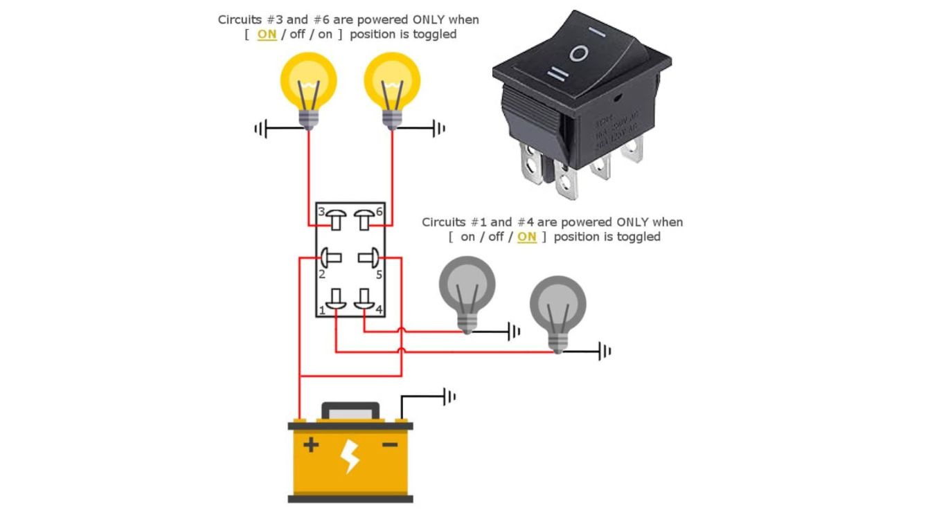
Diagram showing terminal layout and internal connections of a DPDT switch.
How a DPDT Switch Works
Actuation
Moving the toggle or actuator physically shifts two internal conductive wipers (one for each pole).
Connection Change
Each wiper breaks contact with its first output terminal and makes contact with the second output terminal for its respective circuit.
Circuit State
This changes the path of current flow in both circuits simultaneously. The switch has two stable "ON" states (Position A & Position B).
Common Applications of DPDT Switches
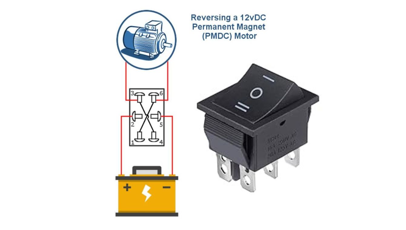
Motor Direction Control (Polarity Reversal)
The most classic use. By wiring a DPDT switch in a specific way, it can reverse the polarity applied to a DC motor, changing its rotation direction.
Signal or Input Selection
Used in audio equipment, test instruments, or control panels to select between two different signal sources for two separate channels or circuits.
Industrial Control Circuits
Employed in machinery to switch between two operating modes (e.g., manual/auto) for two different systems simultaneously, or to control two separate indicator lights.
DPDT vs. Other Common Switch Types
| Switch Type | Poles / Throws | Key Feature | Best For |
|---|---|---|---|
| SPST | Single Pole, Single Throw | Simple on/off for one circuit. | Lamps, basic power control. |
| DPDT | Double Pole, Double Throw | Controls two circuits, each with two paths. Highly versatile. | Motor reversal, signal selection, complex switching. |
| SPDT | Single Pole, Double Throw | Switches one common line between two outputs. | Changeover switching, simple A/B selection. |
| DPST | Double Pole, Single Throw | Simultaneous on/off for two isolated circuits. | Safely disconnecting both line and neutral in an appliance. |
Why Choose WEUP for Your DPDT Switch Needs?
As your reliable partner with over two decades of expertise in premium switch manufacturing, WEUP delivers DPDT switches built for performance and durability.
- Standards Compliance: Our products, including DPDT switches, are manufactured under ISO 9001 and certified to international standards like UL and CE.
- Proven Reliability: WEUP switches offer stable performance, helping clients reduce maintenance costs.
- Expert Customization: Need a specific terminal type, actuator, or electrical rating? We provide rapid response and personalized service.

Key Specifications & Selection Guide
What to Consider When Choosing a DPDT Switch
- Current & Voltage Rating: Must exceed your circuit's maximum values.
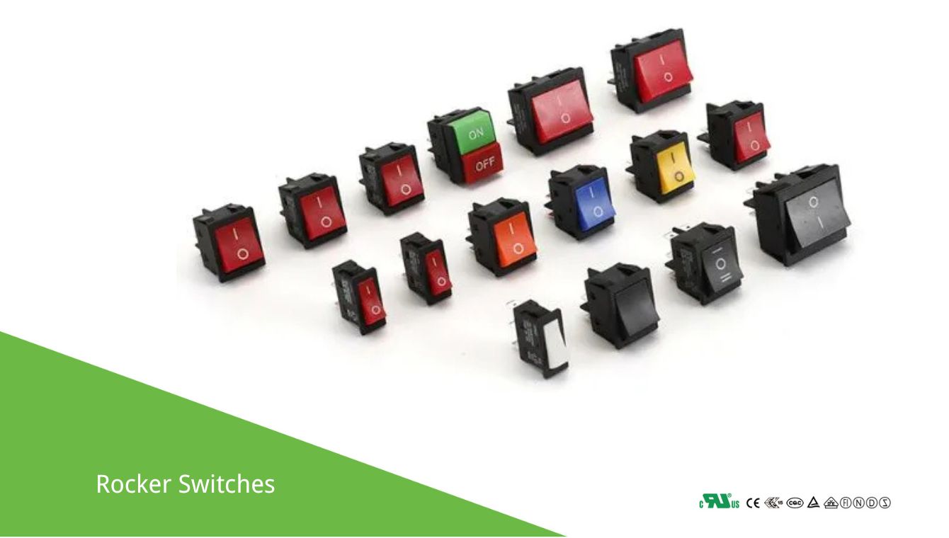
- Actuator Type: Toggle, rocker, paddle, push-button, slide.
- Terminal Type: Solder lugs, screw terminals, quick-connect, PCB pins.
- Mounting Style: Panel mount, PCB mount, snap-in.
- Center-Off Position: Required if a neutral 'off' state is needed between the two active positions.
Typical DPDT Switch Specifications
- Contact ConfigurationDPDT
- Current Rating5A - 20A (common range)
- Voltage Rating125VAC / 250VAC (or higher)
- Electrical Life10,000 - 100,000+ operations
- Terminal TypeVaries by model
* Always consult the specific manufacturer's datasheet for exact ratings and dimensions.
Summary
A Double Pole Double Throw (DPDT) switch is a highly versatile and essential component for controlling two independent circuits with two possible output paths each. Its ability to perform tasks like motor reversal, signal selection, and complex mode switching makes it invaluable across electronics, industrial controls, and automation.
For reliable, certified, and customizable DPDT switches, partner with an industry expert like WEUP.