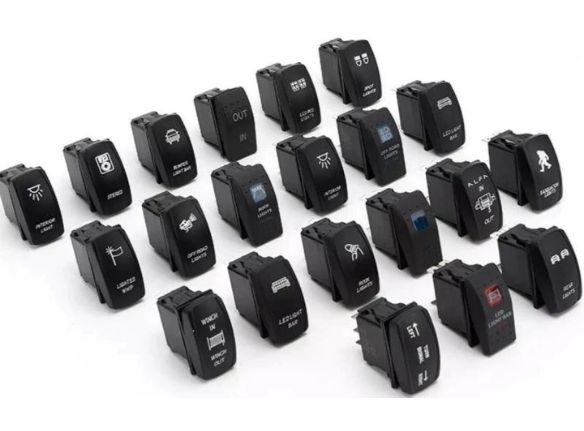
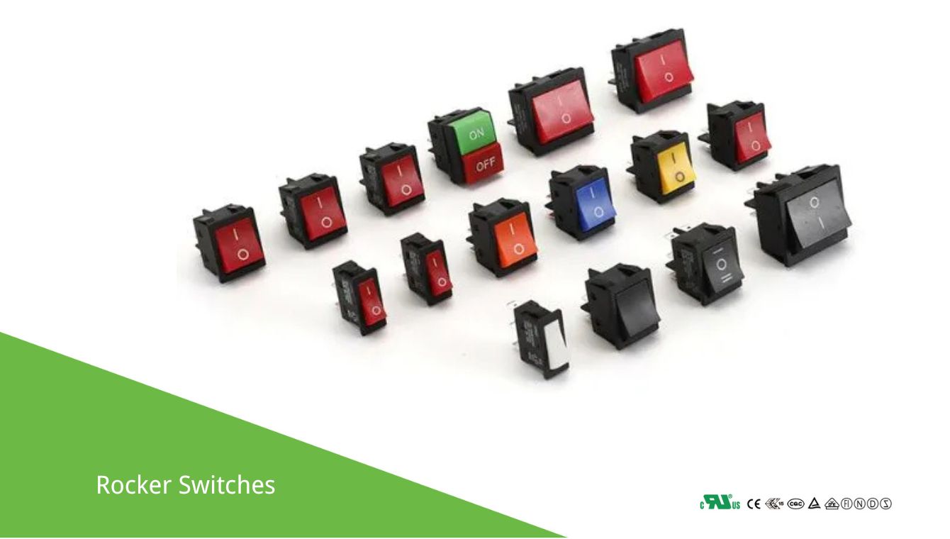
Rocker switches are commonly used in a variety of applications to control power to a device or circuit. Below are several common wiring diagrams for rocker switches, depending on the type of switch and the desired functionality.
Basic Rocker Switch Wiring Diagram
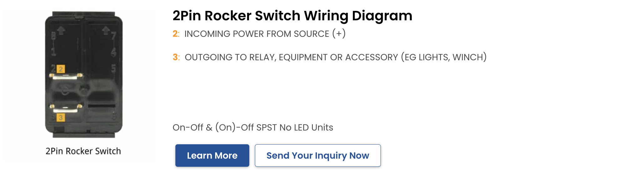
Single Pole Single Throw (SPST)
An SPST switch is the simplest type of rocker switch, with only two terminals. It’s used to control a single circuit:
Connect the power source (+) to one terminal of the switch.
Connect the other terminal of the switch to the load.
Connect the load to the ground (GND).
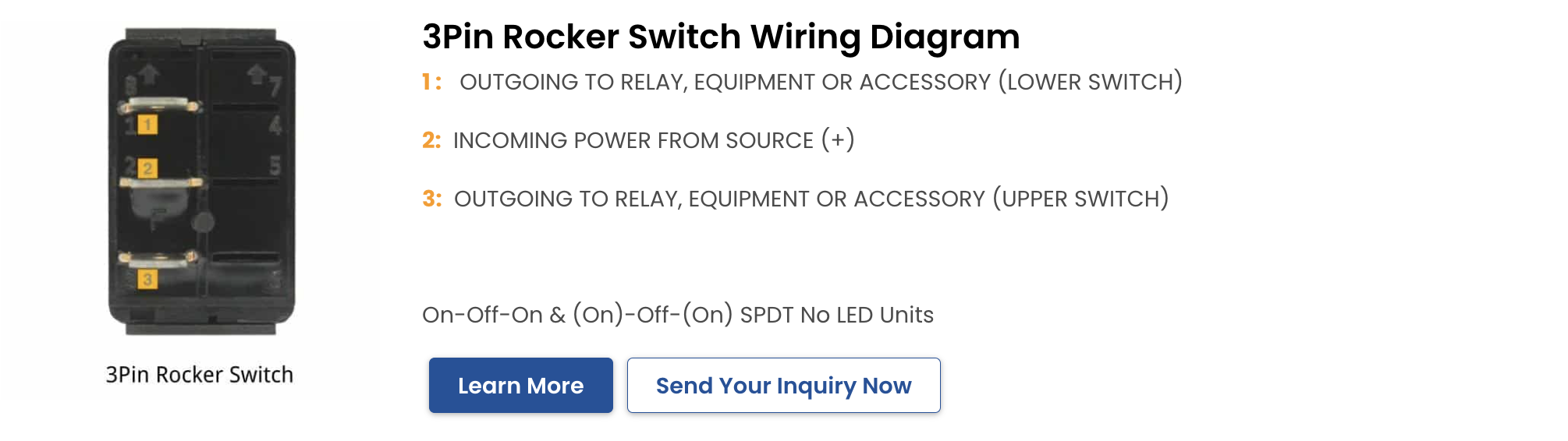
Single Pole Double Throw (SPDT)
An SPDT switch has three terminals and can be used to switch between two circuits:
Connect the power source (+) to the common terminal of the switch.
Connect one of the other terminals to Load 1.
Connect the remaining terminal to Load 2.
Connect the loads to the ground (GND).
Illuminated Rocker Switch Wiring Diagram
SPST with LED Indicator
This type of switch has an internal LED that illuminates when the switch is turned on:
Connect the power source (+) to one terminal of the switch.
Connect the other terminal of the switch to the load.
Connect the load to the ground (GND).
Connect the LED terminal to the load side of the switch.
Double Pole Single Throw (DPST)
A DPST switch is used to control two separate circuits simultaneously with one switch:
Connect Power Source 1 (+) to one terminal of the switch.
Connect the other terminal of the switch to Load 1.
Connect Load 1 to the ground (GND).
Connect Power Source 2 (+) to another terminal of the switch.
Connect the other terminal of the switch to Load 2.
Connect Load 2 to the ground (GND).
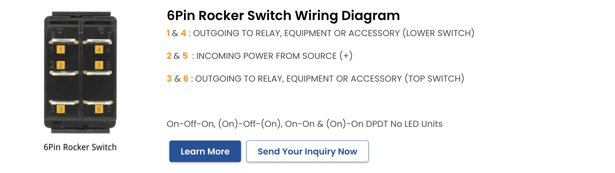
Double Pole Double Throw (DPDT)
A DPDT switch can control two circuits and switch them between two different positions: