
Ultimate Guide to Micro Switch Wiring
A comprehensive guide to understanding, installing, and troubleshooting micro switch wiring for optimal performance and reliability.
Professional Tip: Proper wiring is crucial for switch longevity and safety. Follow this guide carefully for best results.
1. What is a Micro Switch?
A micro switch, also known as a miniature snap-action switch, is an electrical switch that requires very little physical force to activate. These switches are characterized by their small size and precise operation, making them ideal for applications requiring reliability and longevity.
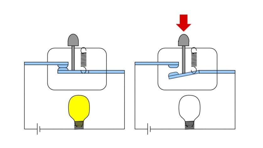
Micro switches feature a spring-loaded lever or button that “snaps” between open and closed positions with minimal movement, providing tactile feedback and consistent performance over millions of cycles.
- Precise Operation: Actuates with minimal force (typically 5-50g)
- Long Lifespan: Rated for 1-10 million operations
- Rapid Response: Fast switching speeds
- Versatile Applications: Used in appliances, industrial controls, automotive systems, and more
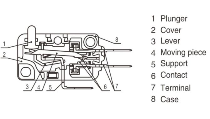
Typical micro switch components and internal mechanism
2. Micro Switch Wiring Basics
⚠️ Important Considerations Before Wiring
- Always verify voltage and current ratings before installation
- Ensure proper insulation and strain relief for wires
- Use appropriate wire gauges for the application
- Follow local electrical codes and regulations
| Wire Color | Function | Typical Connection | Notes |
|---|---|---|---|
| Brown | Live/Phase (L) | Common Terminal (C) | Always hot wire when switch is closed |
| Blue | Neutral (N) | Normally Open (NO) | Connected when switch is activated |
| Green/Yellow | Ground/Earth | Switch Housing | Safety connection only |
| Black | Load/Switch Leg | Normally Closed (NC) | Connected when switch is NOT activated |
3. Terminal Types and Connections
Screw Terminals
- Most common terminal type
- Secure connection with screw tightening
- Requires proper torque (typically 0.4-0.6 Nm)
- Suitable for solid and stranded wires
Quick Connect
- Also known as “fast-on” or “tab” terminals
- Uses female spade connectors
- Speeds up installation process
- Common sizes: 0.187″, 0.25″, 4.8mm, 6.3mm
PCB Mount
- Designed for printed circuit boards
- Through-hole or surface mount options
- Automated assembly compatible
- Common in consumer electronics
WEUP Professional Tip
For high-vibration applications, WEUP recommends using screw terminals with locking washers or additional adhesive to prevent loosening over time. Our switches are tested to withstand industrial vibration levels.
ISO 9001 Certified Manufacturing
4. Step-by-Step Wiring Instructions
Power Off and Safety Check
Before beginning any electrical work, ensure the power supply is completely disconnected. Use a voltage tester to confirm no current is present.
⚠️ Safety First: Always lock out and tag out power sources in industrial settings.
Identify Terminals
Locate and identify the three main terminals: Common (C), Normally Open (NO), and Normally Closed (NC). Refer to the switch datasheet or markings.
                  C = Common (Input)

                  NO = Normally Open (Output when activated)

                  NC = Normally Closed (Output when not activated)
Prepare Wires
Strip approximately 6-8mm (1/4″) of insulation from wire ends. For screw terminals, twist strands tightly. For quick-connect, crimp appropriate connectors.
Connect Wires to Terminals
Connect the power source to the Common terminal. Connect the load (device to be controlled) to either NO or NC terminal based on desired operation mode.
For NO Operation:
Load connected to NO terminal will only receive power when switch is activated.
For NC Operation:
Load connected to NC terminal will receive power until switch is activated.
Secure and Test
Ensure all connections are tight and secure. Apply power and test the switch operation. Verify the load operates correctly in both switch states.
WEUP Quality Assurance: All WEUP switches undergo 100% functional testing before shipment, ensuring reliable performance from installation.
5. Circuit Diagrams and Configurations
SPST (Single Pole, Single Throw)
Wiring Instructions:
- Connect power source to Common terminal
- Connect load to Normally Open terminal
- Ground switch housing if metal enclosure
Applications:
- Basic on/off control
- Limit switches
- Door interlock switches
SPDT (Single Pole, Double Throw)
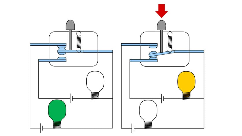
Wiring Instructions:
- Power source to Common terminal
- Load 1 to Normally Open terminal
- Load 2 to Normally Closed terminal
- Use for changeover applications
Applications:
- Motor direction control
- Two-circuit selection
- Fail-safe systems
Advanced Wiring Configurations
Series Connection
Multiple switches connected in series for AND logic operation. All switches must be activated for circuit completion.
Parallel Connection
Switches connected in parallel for OR logic operation. Any switch activation completes the circuit.
Latching Circuit
Uses a relay with micro switch to maintain state after momentary activation. Common in control panels.
6. Safety Precautions
⚠️ Critical Safety Guidelines
Electrical Safety
- Always de-energize circuits before working
- Use appropriate personal protective equipment (PPE)
- Verify circuit isolation with proper test equipment
- Never exceed switch voltage/current ratings
Installation Safety
- Ensure proper mounting and alignment
- Use strain relief for wires
- Protect against environmental factors
- Follow manufacturer torque specifications
Voltage Ratings and Categories
| Application | Typical Voltage | Insulation Class |
|---|---|---|
| Low Voltage Control | 24V DC/AC | Basic |
| Residential | 120/240V AC | Reinforced |
| Industrial | 480V AC | Double |
Environmental Protection
IP Ratings
Choose appropriate IP (Ingress Protection) rating for your environment:
- IP40: Protected against solid objects >1mm
- IP65: Dust tight and protected against water jets
- IP67: Protected against temporary immersion
Temperature Range
WEUP switches operate from -40°C to +85°C (-40°F to +185°F) with proper derating at extremes.
ss=”px-4 py-3 text-left text-sm font-semibold text-gray-900″>Problem
WEUP Support Services
Our technical support team is available to help with complex wiring challenges. With over 20 years of switch manufacturing experience, we provide:
Free wiring diagram assistance
Application-specific recommendations
Custom switch design service
Rapid response within 24 hours
8. Industry Standards and Certifications
Global Standards Compliance
Quality Management System Certified
Underwriters Laboratories Safety
European Conformity Marking
Restriction of Hazardous Substances
WEUP’s Role in Standards Development
As an industry leader for over two decades, WEUP actively participates in the formulation of national switch industry standards in China. Our expertise contributes to:
- Safety requirements for electrical switches
- Performance testing methodologies
- Environmental durability standards
- Quality assurance protocols
Your Reliable Partner for Premium Switches
With over 20 years of experience and international certifications, WEUP provides switches that combine reliability, performance, and value. Our products help reduce maintenance costs by up to 15% through stable performance and extended lifespan.
Quality Assurance
100% functional testing with ISO 9001 certified processes
Custom Solutions
Personalized customization to meet your specific requirements
Technical Support
Expert assistance with wiring, installation, and troubleshooting
Contact WEUP Today
Manufacturing Facility
Building 3, Huayi E-commerce Park
Chengnan Street, Yueqing, Zhejiang
China, 325608