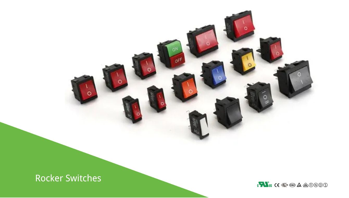
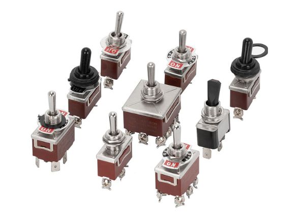
How to wire a 3 prong 12v Illuminated rocker switch?
Okay, wiring a 3-prong 12V illuminated rocker switch is a common task. These switches typically have:
- Power In (Supply/Line): Where 12V+ from your battery/power source connects.
- Load Out (Accessory): Where 12V+ goes to the device you want to control (light, fan, etc.).
- Ground (Negative): For the switch’s internal LED illuminator.
Common Pin Identification (Always verify if possible!):
- Brass/Gold Pin: Often the Ground terminal.
- Silver Pins (x2): One is Power In, the other is Load Out.
- The middle silver pin is frequently the Power In.
- The silver pin furthest from the Ground pin (or closest to where the “ON” position rocks down) is often the Load Out.
Here’s the typical wiring diagram:
Step-by-Step Wiring Instructions:
- SAFETY FIRST! Disconnect the negative terminal of your 12V battery or turn off your power supply before doing any wiring.
- Identify the Pins:
- Look for markings on the switch body (e.g., numbers, symbols like “+”, “L”, ground symbol).
- If no markings, the brass-colored pin is almost always Ground.
- The other two silver pins are for power.
- If you’re unsure, you can test with a multimeter (continuity mode) when the switch is disconnected from power. With the switch in the “ON” position, there should be continuity between the Power In and Load Out pins. The remaining pin is Ground.
- Connect the Ground (for the Switch’s LED):
- Run a wire from the Ground pin (often brass, typically pin #3 or marked with a ground symbol) on the switch to a good chassis ground point or directly to the negative (-) terminal of your 12V battery.
- Connect the Power In:
- Run a wire from your fused 12V positive (+) source to the Power In pin (often the middle silver pin, typically pin #1) on the switch.
- FUSE: This is critical. Choose a fuse rated appropriately for the device you are powering, not the switch itself. The fuse protects the wiring and device from overcurrent.
- Connect the Load Out:
- Run a wire from the Load Out pin (often the silver pin closest to the “ON” position or furthest from ground, typically pin #2) on the switch to the positive (+) terminal of the device you want to control.
- Connect the Device’s Ground:
- Run a wire from the negative (-) terminal of your device to the same chassis ground point or the negative (-) terminal of your 12V battery (same place as the switch’s ground).
How it Works:
- When the switch is OFF, the circuit between “Power In” and “Load Out” is broken. The device is off, and the switch’s LED is off.
- When the switch is ON, it connects “Power In” to “Load Out.”
- Current flows from the battery, through the fuse, into the “Power In” pin.
- It then flows out the “Load Out” pin to your device.
- The device’s ground completes the circuit back to the battery.
- Simultaneously, the switch’s internal LED gets power from the “Power In” (or sometimes “Load Out” internally) and is grounded via the “Ground” pin, causing it to illuminate.
Important Considerations:
- Fuse: Always use an appropriately sized fuse on the positive line feeding the switch. This protects your wiring and device from short circuits.
- Wire Gauge: Use wire gauge appropriate for the current draw of your load. Thicker wire for higher current.
- Connectors: Use good quality connectors (spade, ring, butt connectors) and ensure they are well-crimped or soldered for reliable connections.
- Polarity: While the switch itself might not be polarity sensitive (except for the LED ground), the device you’re powering (especially LEDs) will be.
- Verification: If your switch came with a diagram, use that! If not, the common configuration described above is usually correct, but testing pins with a multimeter is the best way to be certain.
Troubleshooting:
- Switch doesn’t light up, but device works: Check the switch’s ground connection.
- Device doesn’t work, but switch lights up (if it’s designed to light when power is available, not just when ON): Check wiring to the load and the load’s ground.
- Nothing works: Check your main power source, fuse, and all connections, especially the “Power In” to the switch.
- If pins were misidentified:
- If you swap “Power In” and “Load Out,” the switch will still turn the device ON/OFF, but the LED might not light up correctly (e.g., it might only light when the device is ON, or not at all if the internal LED connection depends on the “Power In” pin).
- If you misconnect the ground, the LED won’t light up.
Always double-check your wiring before reconnecting power!

![Okay, wiring a 3-prong 12V illuminated rocker switch is a common task. These switches typically have: Power In (Supply/Line): Where 12V+ from your battery/power source connects. Load Out (Accessory): Where 12V+ goes to the device you want to control (light, fan, etc.). Ground (Negative): For the switch's internal LED illuminator. Common Pin Identification (Always verify if possible!): Brass/Gold Pin: Often the Ground terminal. Silver Pins (x2): One is Power In, the other is Load Out. The middle silver pin is frequently the Power In. The silver pin furthest from the Ground pin (or closest to where the "ON" position rocks down) is often the Load Out. Here's the typical wiring diagram: +-----------------------+ | 12V Power Source | | (Battery / Power Supply)| +----------+------------+ | (+) | [FUSE]](https://www.cweup.com/wp-content/uploads/2025/05/How-to-wire-a-3-prong-12v-Illuminated-rocker-switch.jpg)


