
7-Pin Rocker Switch Wiring Diagram: Complete Installation Guide
A comprehensive wiring guide for 7-pin rocker switches commonly used in automotive, marine, and industrial applications. Learn proper connections, safety precautions, and troubleshooting tips.
Important Safety Notice
Always disconnect power before working on electrical connections. Use proper tools and personal protective equipment. If unsure, consult a qualified electrician.
Standard 7-Pin Rocker Switch Configuration
7-pin rocker switches offer multiple switching functions in a compact design. Understanding pin functions is crucial for correct installation.
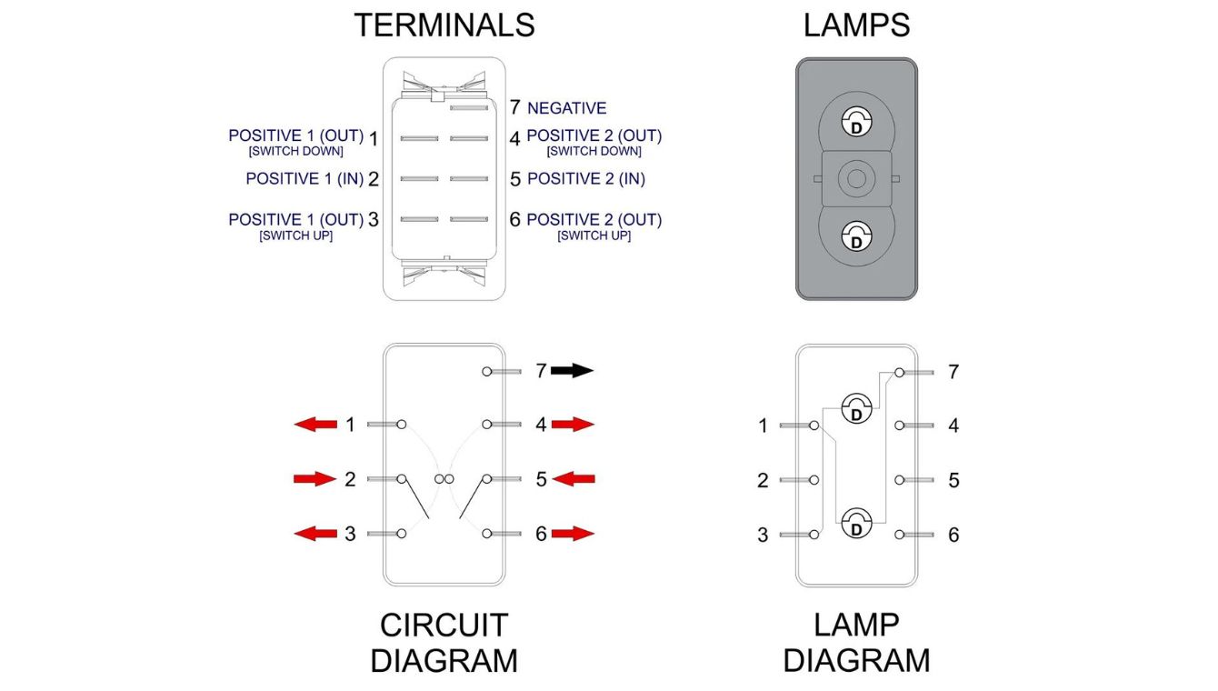
Figure 1: Standard 7-pin rocker switch pin layout and wiring diagram
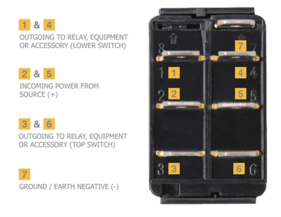
Pin Functions and Descriptions
| Pin Number | Function | Typical Connection | Color Code (Common) |
|---|---|---|---|
| 1 | Power Input (Main) | 12V/24V DC Source | Red |
| 2 | Ground | Chassis Ground | Black |
| 3 | Output 1 (ON Position) | Load 1 (Light, Motor) | Yellow |
| 4 | Output 2 (ON Position) | Load 2 (Accessory) | Green |
| 5 | Illumination + | Panel Light Power | Blue |
| 6 | Illumination – | Panel Light Ground | White |
| 7 | Auxiliary/Indicator | Status Light or Second Function | Orange |
Quick Reference
-
Double-pole double-throw (DPDT) functionality -
Built-in illumination circuit -
Rated 12V/24V DC, 20A max -
IP65 waterproof rating available -
ON-OFF-ON or ON-ON configurations
Tools Required
- • Wire strippers/cutters
- • Crimping tool and connectors
- • Multimeter for testing
- • Soldering iron (optional)
- • Heat shrink tubing
- • Screwdrivers
Need Custom Wiring Solution?
WEUP provides custom 7-pin rocker switches with specific wiring configurations for your application.
Step-by-Step Wiring Instructions
Power Disconnection
Disconnect the negative terminal of the battery or main power source to prevent short circuits or electrical shock during installation.
Warning: Never work on live circuits. Verify power is off with a multimeter before proceeding.
Switch Mounting
Cut appropriate panel opening (typically 22×30mm or as per switch dimensions). Insert switch from front, secure with mounting bracket from rear.
Wire Preparation
Strip approximately 8-10mm of insulation from each wire end. Use appropriate wire gauge (16-14 AWG for 20A applications). Crimp connectors if required.
Wire Gauge Guide
- • 0-5A: 18 AWG
- • 5-10A: 16 AWG
- • 10-15A: 14 AWG
- • 15-20A: 12 AWG
Color Coding
- • Power: Red
- • Ground: Black
- • Load: Yellow/Green
- • Light: Blue/White
Connection Diagram
Follow this detailed connection sequence for standard ON-OFF-ON 7-pin rocker switches:
| Step | Pin | Connection | Purpose |
|---|---|---|---|
| 1 | Pin 2 | Connect to chassis ground | Switch ground reference |
| 2 | Pin 1 | Connect to fused power source | Main power input |
| 3 | Pin 3 & 4 | Connect to Load 1 and Load 2 | Switch outputs |
| 4 | Pin 5 & 6 | Connect to panel light circuit | Illumination |
| 5 | Pin 7 | Connect to indicator (optional) | Status/auxiliary function |
Pro Tip:
Use a multimeter in continuity mode to verify switch positions before final installation. Test ON-OFF-ON positions correspond to correct pin connections.
Testing & Final Installation
Before securing all connections, perform these tests to ensure proper functionality:
- Reconnect power source and test each switch position
- Verify illumination works with panel lights
- Check for proper grounding (no voltage between ground and chassis)
- Test under load to ensure no voltage drop
- Secure all connections with appropriate fasteners
Success Checklist: All positions function correctly, no flickering illumination, no excessive heat at connections, secure mounting.
Common Applications & Configurations
Automotive Use
- • Fog light control
- • Winch power management
- • Auxiliary light systems
- • Dual battery switching
- • Fan override control
Marine Applications
- • Bilge pump control
- • Navigation light switching
- • Anchor winch control
- • Cabin lighting circuits
- • Dual battery selector
Industrial Equipment
- • Machinery power control
- • Emergency stop circuits
- • Conveyor direction control
- • Dual-speed motor control
- • Safety interlock systems
Troubleshooting Guide
| Problem | Possible Cause | Solution |
|---|---|---|
| No power in any position | • Blown fuse • Incorrect power connection • Faulty ground |
Check fuse, verify 12V at pin 1, test ground continuity |
| One position doesn’t work | • Faulty internal contact • Loose wire connection • Defective load |
Test continuity in that position, check connections, test load separately |
| Illumination not working | • Reverse polarity on pins 5-6 • Burned out LED • No panel light power |
Check polarity, test with 12V directly, verify panel light circuit |
| Switch gets hot | • Excessive current draw • Loose connections • Undersized wiring |
Check amperage, tighten all connections, use proper wire gauge |
| Intermittent operation | • Loose terminal connections • Internal switch wear • Corrosion on contacts |
Secure all connections, test with multimeter, consider replacement |
Premium 7-Pin Rocker Switches from WEUP
As your reliable Chinese partner with over 20 years of switch manufacturing experience, WEUP provides high-quality 7-pin rocker switches with international certifications including ISO 9001, UL, and CE.
Key Advantages
-
Industry Standard Compliance: WEUP participated in formulating national switch industry standards, ensuring reliable performance.
-
International Certifications: All switches meet ISO 9001, UL, and CE standards for quality and safety assurance.
-
Customization Services: Rapid response and personalized customization to meet your specific application requirements.
-
Proven Reliability: Our switches maintain stable performance, helping customers reduce maintenance costs by up to 15%.
Technical Specifications
-
Electrical Rating
20A @ 12V DC, 15A @ 24V DC -
Contact Resistance
<10mΩ -
Insulation Resistance
>100MΩ -
Dielectric Strength
1500V AC/minute -
Mechanical Life
50,000 cycles minimum -
Operating Temperature
-30°C to +85°C -
Protection Rating
IP65 (waterproof versions)
Need custom wiring solutions or bulk pricing for your project?
Building 3, Huayi E-commerce Park, Chengnan Street, Yueqing, Zhejiang, China, 325608
Frequently Asked Questions
Can I use a 7-pin rocker switch for AC applications?
Most 7-pin rocker switches are designed for DC applications (12V/24V). Using them with AC power may cause premature failure or safety issues. Always check manufacturer specifications for AC/DC ratings.
What’s the difference between ON-OFF-ON and ON-ON configurations?
ON-OFF-ON has a center OFF position with two active positions. ON-ON has two active positions with no OFF position in between. Choose based on whether you need an OFF state between functions.
How do I wire the illumination circuit independently?
Connect pin 5 to a separate 12V source (like panel lights circuit) and pin 6 to ground. This allows illumination to work independently of switch position. Some switches have illumination only when ON.
Can I parallel two switches for higher current?
Not recommended. Paralleling switches doesn’t guarantee equal current sharing. Instead, use a relay controlled by the switch for high-current applications exceeding the switch rating.
What maintenance do rocker switches require?
Quality rocker switches are maintenance-free. For harsh environments, periodically check for corrosion at terminals. Avoid excessive force when operating and keep free of debris.